

 English
 русский
 Español
 Português
 عربى
عربى
 Türk
Türk








+86 18395326713
Jul 10, 2026
Harsh environments place continuous mechanical, thermal, and chemical stress on pumping equipment. Unlike surface-mounted units, submersible pumps operate fully immersed, which changes how heat is dissipated, how seals behave under pressure, and how particulate matter interacts with internal components. Evaluating performance in these conditions requires looking beyond flow rate and head, into material fatigue, seal degradation, and motor cooling behavior over extended duty cycles.
Applications such as mining dewatering, municipal sewage handling, agricultural irrigation, and deep well extraction each introduce distinct stressors. A pump rated for clean water service will behave very differently when exposed to abrasive slurry, corrosive chemicals, or fluctuating water tables.
Motor windings generate heat during operation, and in a submersible design, the surrounding fluid typically serves as the primary coolant. In environments where fluid temperature is already elevated, such as geothermal wells or industrial discharge points, the thermal margin available for cooling shrinks significantly. Motors without adequate thermal protection can experience insulation breakdown, leading to premature winding failure.
Sand, grit, and suspended solids accelerate wear on impellers, wear rings, and mechanical seals. In a submersible water pump used for well applications, sand ingress is one of the most common causes of premature bearing failure. Abrasion resistance depends heavily on impeller material hardness and clearance tolerances.
Wastewater, brackish water, and industrial effluent often contain dissolved salts, acids, or hydrogen sulfide gas. These conditions accelerate galvanic corrosion, particularly at dissimilar metal junctions such as shaft couplings or fastener interfaces.
Deep installations subject seals and housings to sustained hydrostatic pressure. As depth increases, the pressure differential across the motor seal grows, raising the risk of water ingress if seal integrity is compromised.
| Pump Type | Primary Application | Environmental Tolerance |
|---|---|---|
| Submersible Sewage Pump | Wastewater, municipal lift stations | High solids handling, corrosion resistant |
| Deep Well Submersible Pump | Groundwater extraction | High pressure, moderate sand tolerance |
| Electric Submersible Pump | Oil field and industrial fluid transfer | High temperature, chemical exposure |
| Submersible Sump Pump | Basement and drainage systems | Intermittent duty, low solids |
| Industrial Submersible Pump | Mining and construction dewatering | Heavy abrasion, continuous duty |
Dual mechanical seals with an oil-filled barrier chamber reduce the likelihood of water reaching motor windings if the primary seal fails.
Hardened impeller materials, such as high-chrome alloys, extend service intervals in abrasive slurry applications.
Moisture sensor probes installed in the seal chamber provide early warning before catastrophic motor failure occurs.
Thermal overload protection automatically shuts down the motor when winding temperature exceeds safe thresholds.
Cable entry sealing prevents capillary water migration along the power cable into the motor housing.
Selection should begin with a clear definition of the fluid characteristics and duty cycle, not just the desired flow rate. The following considerations help narrow the decision:
Flow and head define the operating point on a pump curve, and mismatched selection is a common cause of inefficiency. A pump running far from its best efficiency point experiences higher vibration, increased bearing load, and accelerated seal wear.
| Application | Typical Flow Range | Typical Head Range |
|---|---|---|
| Residential Sump Drainage | Low | Low to moderate |
| Agricultural Irrigation | Moderate to high | Moderate |
| Municipal Sewage Lift Station | High, variable | Moderate to high |
| Deep Well Water Supply | Moderate | High |
Operators should size pumps to run near the midpoint of the efficiency curve rather than at its extremes, allowing margin for seasonal flow variation without sacrificing mechanical reliability.
The core distinction lies in placement and priming: submersible units operate fully immersed and are self-priming by design, while standard centrifugal pumps are mounted externally and rely on suction lift, which limits their maximum practical suction height.
| Characteristic | Submersible Pump | Surface Centrifugal Pump |
|---|---|---|
| Mounting Location | Fully immersed in fluid | External, above fluid source |
| Priming Requirement | Self-priming by design | Requires priming or foot valve |
| Noise Level | Lower, dampened by fluid | Higher, airborne noise |
| Cooling Method | Surrounding fluid | Ambient air or external cooling |
| Maintenance Access | Requires extraction from fluid | Readily accessible |
Preventive maintenance reduces unplanned downtime significantly in continuous-duty applications. Key practices include:
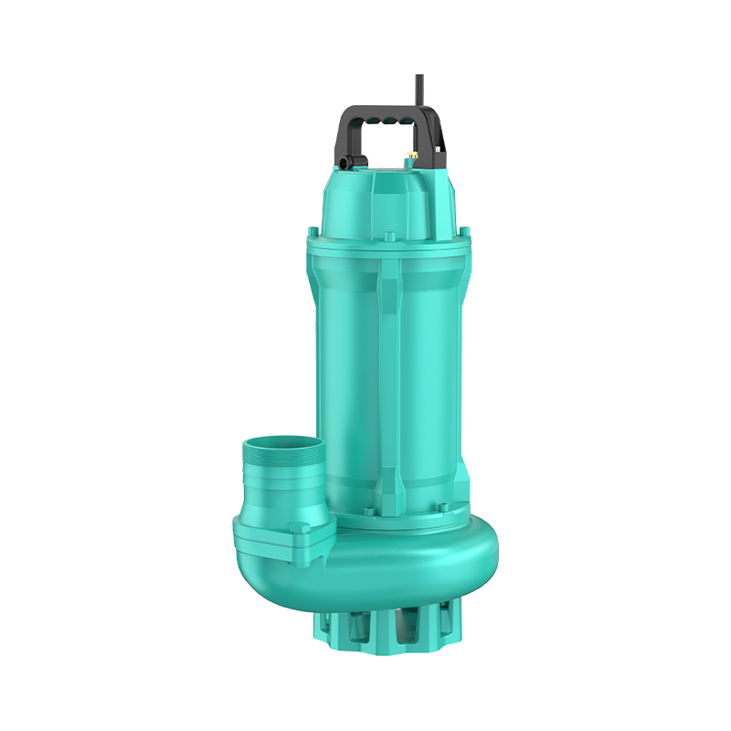
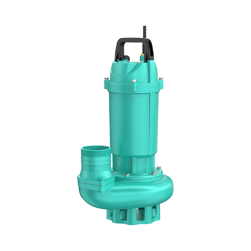
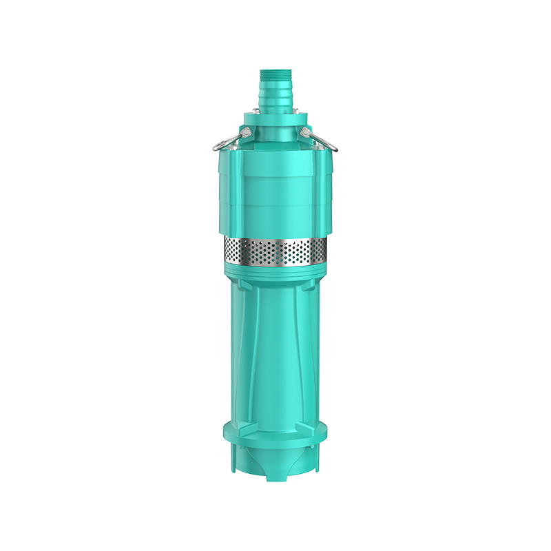
A submersible pump is a sealed unit designed to operate while fully submerged in the fluid it moves. The motor is hermetically sealed and coupled directly to the pump end, pushing fluid to the surface through discharge piping rather than pulling it via suction, which eliminates cavitation risk associated with suction lift limitations.
Selection depends on fluid characteristics, required flow and head, duty cycle, and installation depth. Matching these factors to the correct pump type and material construction is essential for reliable long-term operation.
Common types include sewage pumps for wastewater handling, deep well pumps for groundwater extraction, electric submersible pumps for industrial and oilfield use, sump pumps for drainage, and industrial submersible pumps for mining and construction dewatering.
Submersible pumps operate immersed in fluid and are self-priming, while centrifugal pumps are mounted externally and depend on suction lift, which restricts their maximum practical installation height above the fluid source.
Operators should calculate total dynamic head, including elevation and friction losses, then choose a pump whose performance curve places the operating point near peak efficiency rather than at either extreme of the curve.
Hot News
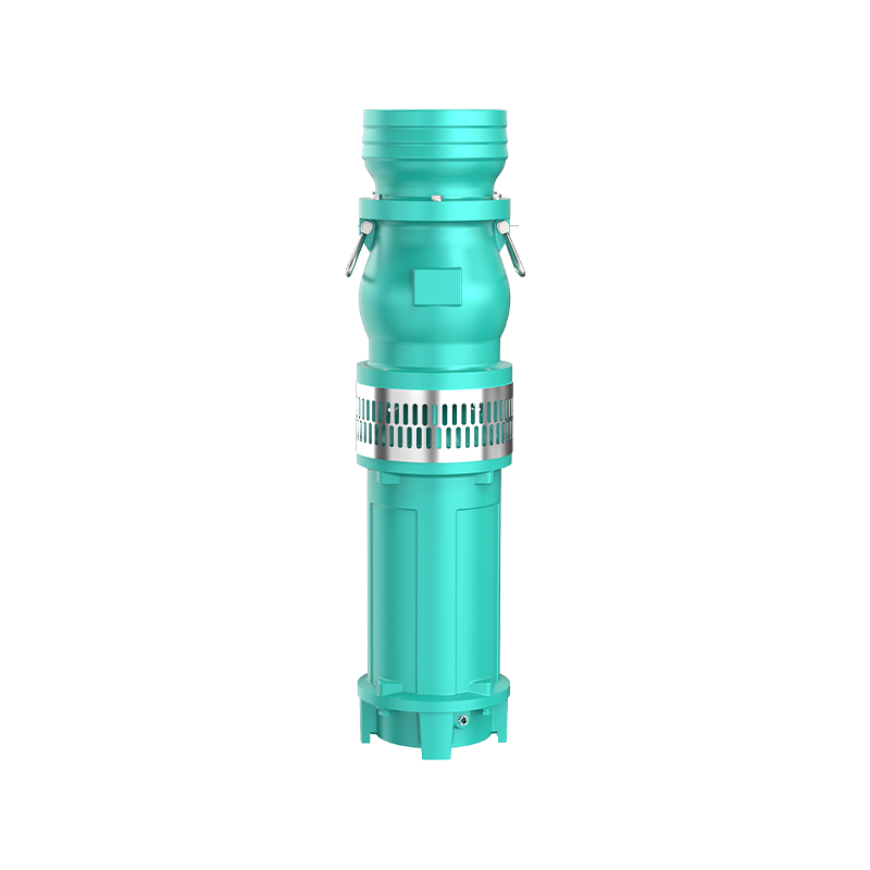 Oil Immersed Submersible Electric Pump: Working Principles, Applications, and Future Trends
Sep 04, 2025
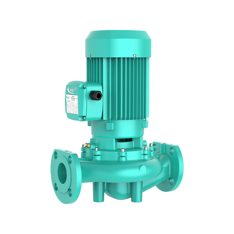 Global Pipeline Centrifugal Pump Industry Update: High-Efficiency Double Suction and Magnetic Drive Technologies Leading the Industrial Water Treatment Revolution
Sep 04, 2025
 Complete Guide to Household Water Pumps: From Selection, Installation to Maintenance, Your Home's 'Water Butler'
Sep 04, 2025
 Can the intelligent automatic self-priming vortex water pump lead a new era in water management?
Sep 04, 2025
Get In Touch

Address 1:
No. 4 Taoyuan Road, Taozhou Town, Guangde City, Xuancheng City, Anhui Province, China
Address 2:
Daxi Town, Wenling City, Taizhou City, Zhejiang Province, China Pump Industry Intelligent Manufacturing Town